 by
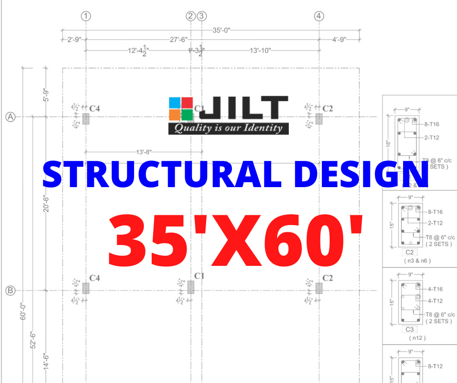
by This article is very important for civil Engineers. In this we have covered complete structrual design of a house. The dimensions of a plot is 35’x60′. This is south face plan and it is as per vastu. First Below you will see the floor plan of a house.
This Structural design of a project is considered as G+2. i.e Four floors. And Steel grade we considered is Fe500. This design is created in Staadpro Software. Staadpro is a software in which you can apply for dead and live loads and take the Structural drawings.
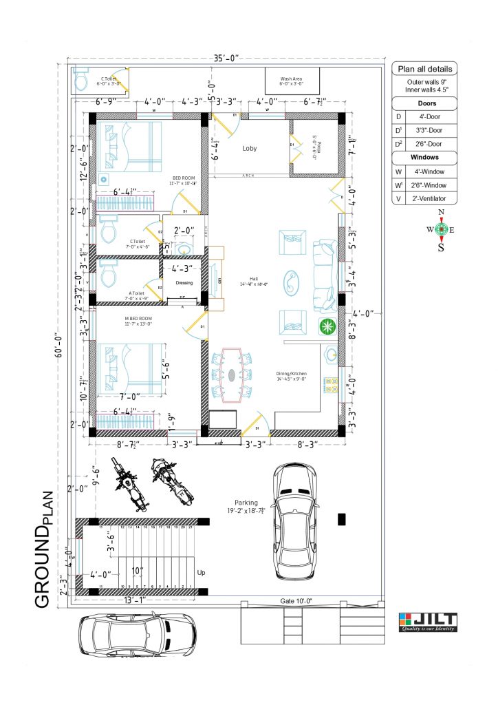
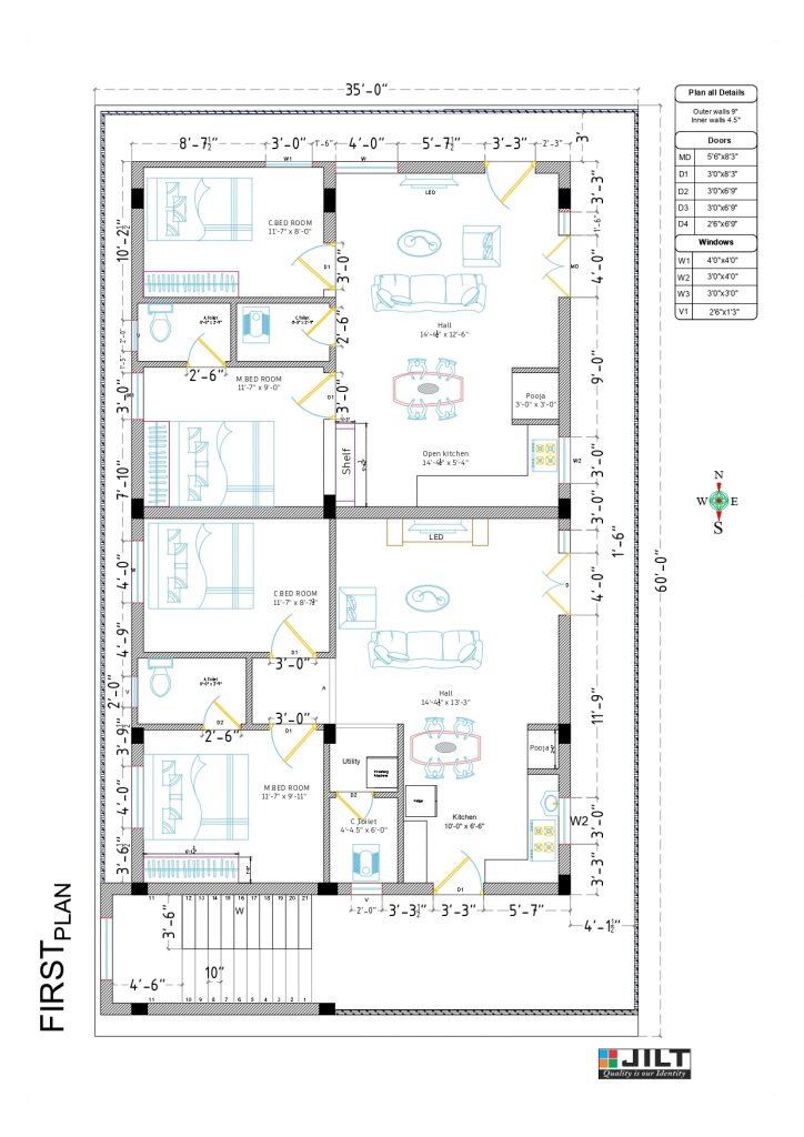
Above images shows the Ground and First Floor Plan of a House. In short you will see the details of plan.
In Ground Floor 2BHK with Car Parking and in First Floor 2BHK two portions.
Now lets see the Structural Design of a Project. In Structural Designs we will see 10 to 20 drawing as per project. Structural Design drawing are as follows
– Column Center Line
– Foundation Layout
– Schedule of Footings and Columns
– Plinth Beam Design
– Column Design
– Beam Designs
– Slab Shuttering Layouts
– Staircase Designs
All drawing related to structure will be consider in Structural Design. Below shows the images of all structural drawing of a project
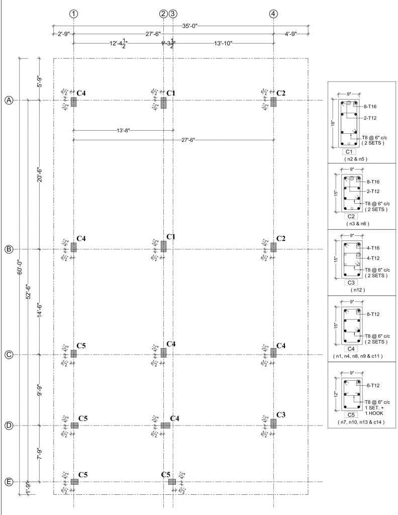
Column Center Line
This drawing shows the column center line of a project. This drawing is very important and is used to start the project.
By using this drawing an engineer will make a center line marking of a project on site then he will follow the foundation layout drawings.
In this drawing you can see the 5 different types of columns i.e C1, C2, C3, C4 and C5. You can see the Number of steel rods in each column.
Foundation Layout
In this drawing you can see the Dimensions of each footing. As per the load the footings of project are different as you can see in the image.
By marking footings as per the dimensions shown in the diagram an engineer will start the digging.

Schedule of Columns & Footing
In this diagram you can see the required number of steel bars in each column or footings.
After digging of footings by seeing this drawing the site engineer will guide mestry for steel work.
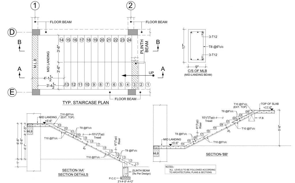
Typical Staircase and Rainforcement Details
In this drawing all details of staircase is availabe. This is a typical staircase drawing it means the drawing is same for all floors.
You can see the number of steel bars used and its diameter.
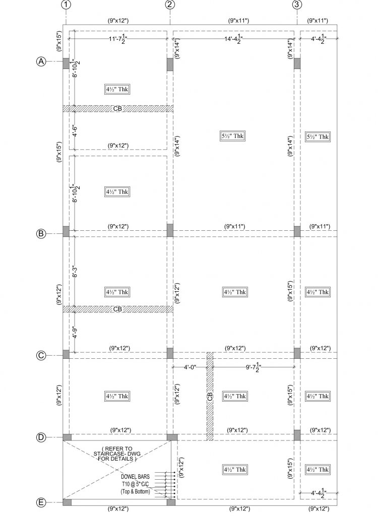
First Slab Shuttering Layout
In this diagram you will see the project first slab shuttering layout.
You can see the Beams location, Concealed beam locations and slab thikness.
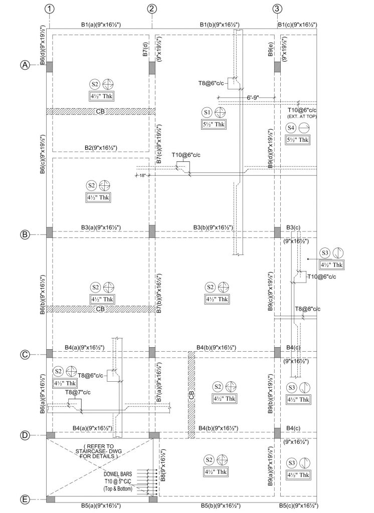
First Slab Rainforcement Details
This image shows the rainforcement details of first slab of a project.
This dragram has details that whether slab is one way or two way. The Steel diameter for Main bar and distribution bar. And in this diagram you can see the distance between the main and distribution bars.
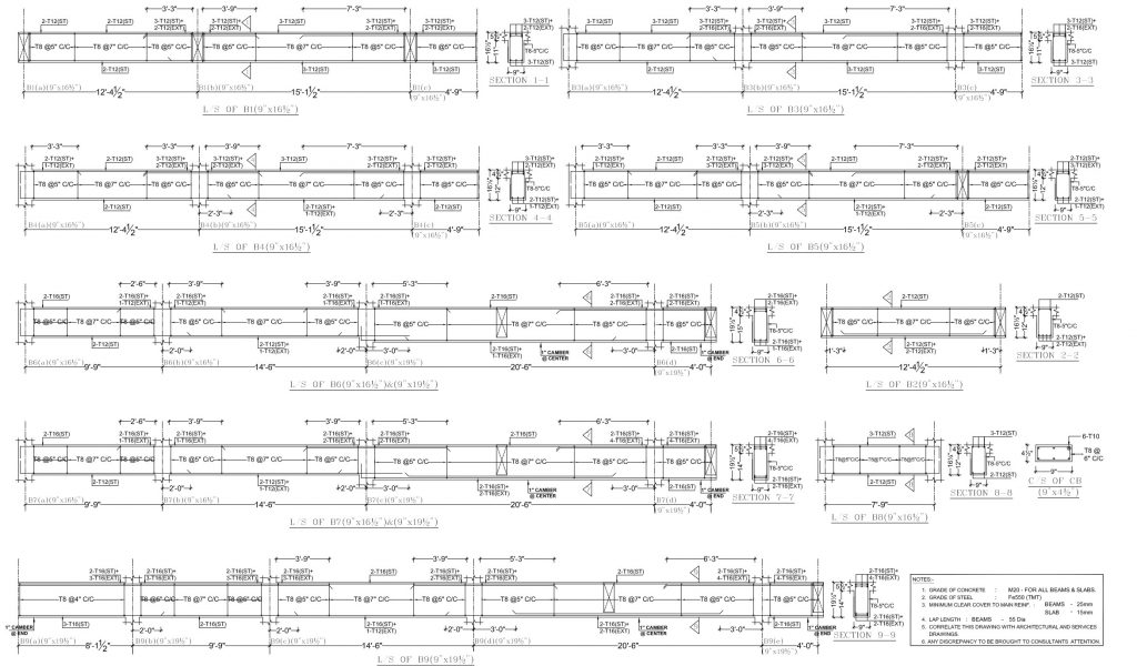
Fist Slab Beam Rainforcement Details
In this dragram you will see all the details of first slab beam. You will see the section dragram of beams. We have different beams for this project as per the load distribution the beam sizes and Rainforcement in the beams are different.
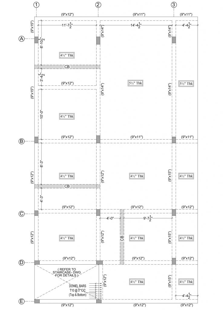
Typical Slab Shuttering Layout
In this image you will see the project typical slab shuttering layout.
You can see the Beam sizes and location, Concealed beam locations and slab thikness.
Typical Slab Rainforcement Details
This image shows the rainforcement detials of typical floor of a project.
Same as the first slab rainforcement diagram you will see the that one way or two way slab and slab thikness, In slab which diameter is using. and distance between steel bars etc…
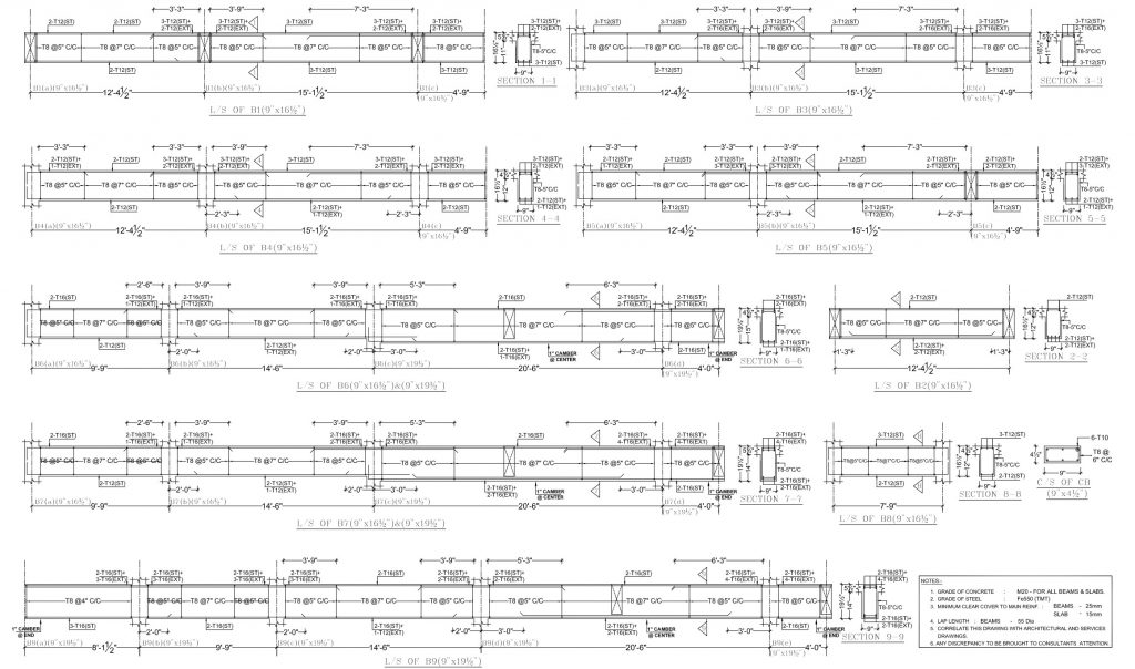
Typical Slab Beam Rainforcement Details
This diagram show the section of all beams. As per the load distribution in beams we will use different diamenter steel bars as per the design.
As the design is considered for G+2. The first and second floor all drawing are typical drawings i.e the drawing for first and second floor is same.